
Page 56 - Industrial Plants
P. 56
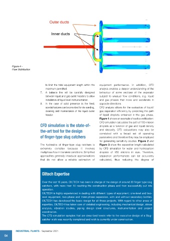
Figure 4 -
          Flow Distribution


                                 to limit the total equipment length within the   equipment performance. In addition, CFD
                                 maximum permitted.                    analysis enables a deeper understanding of the
                             7.  A balance line will be carefully designed   behaviour of some sections of the separator
                                 between liquid and gas outlet headers to allow   subject to unusual flow conditions, e.g. liquid
                                 installation of liquid level instrumentation.   and gas phases that move and accelerate in
                             8.  In the case of solid presence in the feed,   opposite directions.
                                 special features can be provided for de-sanding,   CFD analysis allows for the evaluation of liquid/
                                 cleaning and maintenance of the liquid outlet   gas separation efficiency by predicting the path
                                 header.                               of liquid droplets entrained in the gas phase.
                                                                       Figure 1 shows an example of such a verification:
                                                                       CFD simulation calculates the path of 150-micron
                             CFD simulation is the state-of-           droplets as a function of gas and liquid density
                             the-art tool for the design               and viscosity. CFD calculations may also be
                                                                       correlated with a broad set of operating
                             of finger-type slug catchers              parameters and therefore they may be employed
                                                                       for generating sensitivity studies. Figure 2 and
                             The hydraulics of finger-type slug catchers is   Figure 3 show the separation length calculated
                             extremely complex because it involves     by CFD simulation for water and hydrocarbon
                             multiphase flow in transient conditions. Simplified   droplets of 150 microns in size. Therefore,
                             approaches generally introduce approximations   separation performances can be accurately
                             that do not allow a reliable estimation of   calculated, thus reducing the degree of


                              Oiltech Expertise


                              Over the last 15 years, OILTECH has been in charge of the design of around 30 finger-type slug
                              catchers, with more than 10 reaching the construction phase and then successfully put into
                              operation.
                              OILTECH is highly experienced in dealing with different types of equipment: one-level and two-
                              level equipment, two-phase and three-phase separation, with and without secondary bottles.
                              OILTECH has developed the basic design for all these projects. With regard to other areas of
                              expertise, OILTECH has taken care of detailed engineering, including mechanical design, stress
                              analysis, vibration studies, piping design steel structures, instrumentation and project
                              coordination.
                              The CFD simulation samples that are described herein refer to the executive design of a Slug-
                              catcher wich was recently completed and wich is currently under construction.


            IndustrIal Plants - September 2021
    54