
Page 56 - Industrial Plants
P. 56
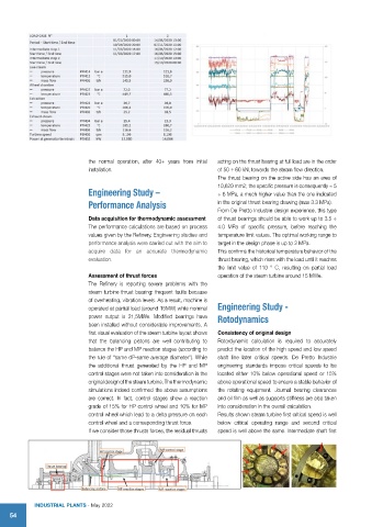
the  normal  operation,  after  40+  years  from  initial   acting on the thrust bearing at full load are in the order
                             installation.                             of 50 ÷ 60 kN, towards the steam flow direction.
                                                                       The thrust bearing on the active side has an area of
                                                                       10,620 mm2; the specific pressure is consequently ≈ 5
                             Engineering Study –                       ÷ 6 MPa, a much higher value than the one indicated

                             Performance Analysis                      in the original thrust bearing drawing (max 3.3 MPa).
                                                                       From De Pretto Industrie design experience, this type
                             Data acquisition for thermodynamic assessment   of thrust bearings should be able to work up to 3.5 ÷
                             The performance calculations are based on process   4.0 MPa of specific pressure, before reaching the
                             values given by the Refinery. Engineering studies and   temperature limit values. The optimal working range to
                             performance analysis were carried out with the aim to   target in the design phase is up to 2 MPa.
                             acquire data for an accurate thermodynamic   This confirms the historical temperature behavior of the
                             evaluation.                               thrust bearing, which rises with the load until it reaches
                                                                       the limit value of 110 ° C, resulting on partial load
                             Assessment of thrust forces               operation of the steam turbine around 15 MWe.
                             The Refinery is reporting severe problems with the
                             steam turbine thrust bearing: frequent faults because
                             of overheating, vibration levels. As a result, machine is
                             operated at partial load (around 15MW) while nominal  Engineering Study -
                             power output is 21,5MWe. Modified bearings have   Rotodynamics
                             been installed without considerable improvements. A
                             first visual evaluation of the steam turbine layout shows   Consistency of original design
                             that the balancing pistons are well contributing to   Rotordynamic calculation is required to accurately
                             balance the HP and MP reaction stages (according to   predict the location of the high speed and low speed
                             the rule of “same dP-same average diameter”). While   shaft line later critical speeds. De Pretto Industrie
                             the additional thrust generated by the HP and MP   engineering standards impose critical speeds to be
                             control stages were not taken into consideration in the   located either 10% below operational speed or 15%
                             original design of the steam turbine. The thermodynamic   above operational speed to ensure a stable behavior of
                             simulations indeed confirmed the above assumptions   the  rotating  equipment.  Journal  bearing  clearances
                             are correct. In fact, control stages show a reaction   and oil film as well as supports stiffness are also taken
                             grade of 15% for HP control wheel and 10% for MP   into consideration in the overall calculation.
                             control wheel which lead to a delta pressure on each   Results shown steam turbine first critical speed is well
                             control wheel and a corresponding thrust force.  below  critical  operating range and second  critical
                             If we consider those thrusts forces, the residual thrusts   speed is well above the same. Intermediate shaft first


            IndustrIal Plants - May 2022
    54