Page 76 - 95
P. 76

TECHNOLOGIES


       Fig. 1 - Comparison of
       temperature link and catalyst
       lifetime for ESP vs. UCF vs.
       Fabric Filter


                                                                      Like the fabric (bag) filter, the ceramic filter has a
                                                                      tube-like shape (candle) as shown in Fig. 2 and
                                                                      works on the principle of barrier filtration. Howev-
                                                                      er, in contrast to fabric filter material, the ceramic
                                                                      fibers result in a rigid filter wall, which allows the
                                                                      filter to build and maintain a residual layer, even
                                                                      in times of pulse jet cleaning as shown in Fig. 3.

                                                                      This  special  characteristic  permanently  moves
                                                                      the barrier filtration zone into the filter cake, pre-
                                                                      venting penetration of any dust constituents into
                                                                      the filter wall. While this characteristic enables
                                                                      reduction of PM  and PM  to >99.99% reduc-
                                                                                           2.5
                                                                                   10
                                                                      tion levels, when catalytic filters are preferred,
                                                                      it fully protects the catalyst against plugging or
       Fig. 2 - Ceramic filter                                        poisoning, which  is  finely  dispersed on the ce-
       candles of different length                                    ramic  fibers inside  the  filter  wall.  This  ensures
                                                                      minimal degradation of the catalyst for the full life
                                                                      of the ceramic filter, significantly minimizing op-
                                                                      erational costs associated with replacement or
                                                                      regeneration of catalysts within traditional SCR
                                                                      systems.

                                                                      The catalyst formulation used within ceramic fil-
                                                                      ters can be tailored to different functionality. Typ-
                                                                      ical catalytic ceramic filters allow the control of
                                                                      organic hazardous air pollutants (O-HAPs), typ-
                                                                      ically from the BTX aromatics group (benzene,
                                                                      toluene and xylene) and aldehydes, together
                                                                      with dioxins and furans by catalytic oxidation.

                                                                      When injecting ammonia or urea, the catalyst will
                                                                      act like a typical SCR technology in controlling
                                                                      NOx with a high efficiency, as shown in Fig. 4,
                                                                      according to following chemical reactions:
                                                                      NO + NO + 2 NH   →    N + 3 H O  (fast)
                                                                                          2
                                                                                    3
                                                                             2
                                                                                                2
                                                                      4 NO + 4 NH +O   → 4 N + 6 H O  (slow)
                                                                                   2
                                                                                          2
                                                                                               2
                                                                                3
                                                                      6 NO + 8 NH     → 7 N +12 H O  (slow)
                                                                          2      3      2     2
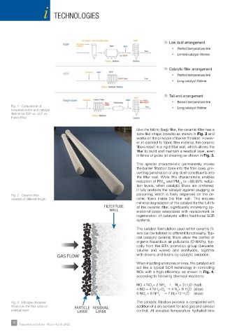
       Fig. 3 - Principle of barrier                                  The catalytic filtration process is completed with
       filtration in the filter cake on                               addition of a dry sorbent for acid gas and aerosol
       residual layer                                                 control. At elevated temperature hydrated lime
       70 70  Impiantistica Italiana - Marzo-Aprile 2022
   71   72   73   74   75   76   77   78   79   80   81